The BALLAST WATER MANAGEMENT-BWM Convention entered into
force on 8 September 2017.
Introduction BWTS
Presently the
IMO urged the ship’s owner’s to concerning about the ballast water treatment
system to avoid the marine biological Pollution caused by the conventional
ballast water exchange system IMO-D1.
Hence the IMO came up with the new regulation to mitigate
such violation is the ballast water treatment IMO-D2 system.
Here you can get the generic working details of ballast
water treatment system (BWTS) or ballast water management system (BWMS) for
your better knowledge of the operation.
IMO-D1: Ballast water exchange method
IMO-D2: Ballast Water Treatment method
IMO-D3: Approval requirements for Ballast Water Management
systems
IMO-D4: Prototype Ballast Water Treatment Technologies
IMO-D5: Review of Standards by the Organization
About BWTS-Ballast Water Treatment System
Total four
types of ballast water treatment system available as of now in the market and
here we will discuss the most commonly used electrolysis and UV Ballast
Water Treatment Method.
- Electrolysis method
- UV treatment method
- Magnetic separation method
- Gas Treatment method
Electrolysis method
The electrolytic method is to add or dosing the chloride/chlorine water in the ballast tank to kill the marine organism.
The electrolysis method is classified by two types
a. Side stream
method
b. Full Stream
method
a. Side stream method
Summary of side stream method:
It consists of the following major unit to achieve the
treated ballast water for the ship’s
- Filtration unit
- Electrolyser unit
- Neutralizer unit
- TRO (Total Residual Oxidant) monitoring unit
Filtration-side stream method
Filtration is
the pre-treatment of the BWTS and the main role of this system is to filter
the marine organism, sediments, and large plankton, a marine organism. It is
equipped with the auto backwashing assembly to pump out the filtered particles
from the filtration unit without interrupting the ballast operation and the
backwash takes place automatically when differential pressure reaches the set
point or the timer set value for the backwashing operation.
The filter
size is about 50-micron candle type and it has the pressure sensor to monitor
the pressure continuously in the filter chamber and followed by some control equipment’s
such as a timer, relay, flow transmitter.
After completion of ballasting de-ballasting operation the
filter unit used to be filled with fresh water in order to protect the filter
corrosion.
Electrolyser-side stream method
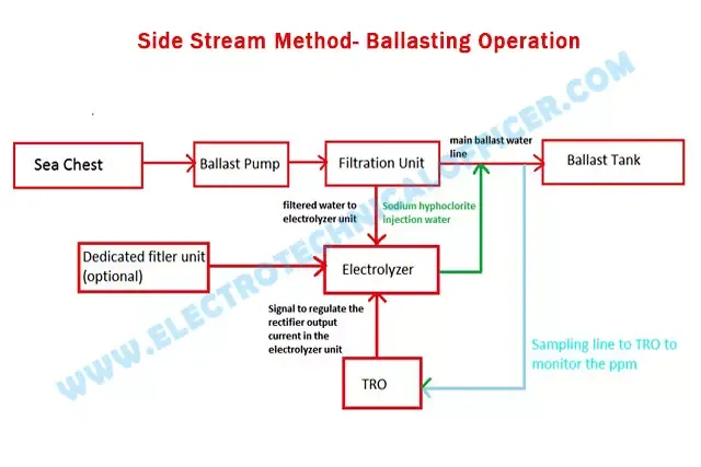
The filtered
water from the main filter unit is fed to the electrolyzer unit or the
dedicated filtration unit (optional) is fitted for the electrolyzer to produce
the oxidant which is Sodium Hypochlorite (disinfectant) NaOCl.
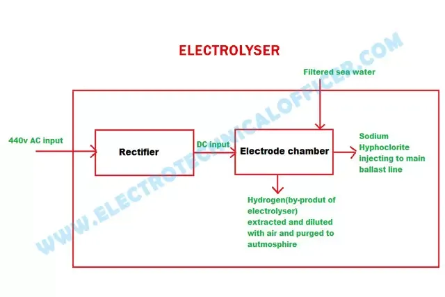
Hydrogen is the by-product of the electrolyser and it’s
extracted from the unit and diluted with air by the help of by gas separator
and electric blower and purged into the safe atmospheric zone.
The generated
Sodium hypochlorite is injected to the main ballast line and it’s reacted in the
pipe with organic and inorganic species such as larva, spores, pathogens, etc.,
The
sampling line from the main ballast line to TRO unit to monitor the oxidant
value which should be in the range of 6.5ppm-9ppm during ballasting extracted
diluted.
Electrolyser operation only during the ballasting operation
NOTE
The
electrolyzer feedwater must be heated up through the heat exchanger if the
actual temperature of the seawater falls below 15oC to avoid the
rectifier high current trips and if the ship enters the freshwater port ship
should be filled up with the saltwater in the dedicated saltwater tank or aft
peak tank prior to entering into the freshwater region, because the saltwater
is most needed for producing the disinfectant.
Neutralizer-side stream method
Neutralizer unit is used
to neutralizing the residual oxidant (chlorite) in the treated ballast water
which can’t discharge overboard directly without neutralized. That the
remaining oxidant might have harmful for the marine organism in the ballast
tank.
Na2s2o3sodium
thiosulfate is the neutralizing agent this powder agent mixed
with water and stored in the form of a solution in the neutralizer tank and kept
ready for injection during de-ballasting, this is called neutralization or
de-chlorination.
Total Residual Oxidant (TRO)-side stream method
The
TRO unit has the two types of chemical solutions in the TRO cabinet to carry out
the chemical calculation of the treated water. Buffer solution and total
chlorine indicators are the two types of chemicals.
Ballasting-side stream method
TRO is used to analyze or
determine the total residual oxidant concentration in the mainline during
ballasting and this monitoring is carried out throughout the ballasting
operation simultaneously transmits the signals to the PLC or control unit.
De-ballasting-side stream method
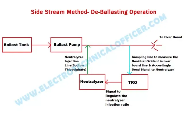
Prior discharge/ de-ballasting the treated water should be
neutralized. During de-ballasting, the
sampling pump sucks the tiny amount of treated water from the de-ballasting
line to TRO analyzer for analyze and determine the residual oxidant value and
send the signal to the control unit. According to the received signal, the from the control unit (PLC) the neutralizer will control the injection ratio of sodium
thiosulfate solution to obtain the target value which is 0.1ppm before it’s
discharged.
Miscellaneous parts
Except for this above mentioned major part
in the BWTS few more parts or sensors are employed in the BWTS operation
- Rectifier used to convert the AC into DC for the electrodes in the electrolyzer
- Control cabinet or PLC panel to carry out the operation with embedded program
- Flow transmitter for various liquid flow measuring and transmitting to the PLC
- Electrolytic injection pump during ballasting operation
- Neutralizer injection pump during de-ballasting operation
- Neutralizing tank to store the sodium thiosulphate solution
- Hydrogen separator with an electric blower to separate the gas from and diluted
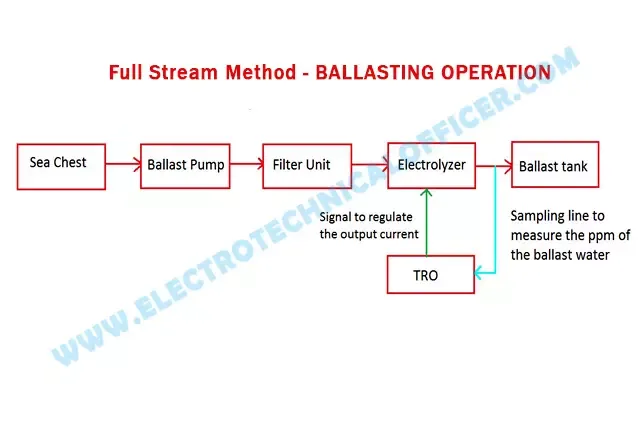
b. Full Stream Method-BWTS
The full stream operation is almost
same as side stream with small changes like the electrolyzer unit installed
consecutively in the main ballast line instead of away in the line like side
stream.
De-ballasting operation is the same as the side stream
UV TREATMENT
Ultra
Violet disinfection method consists of the following major processor parts to achieve
the treated ballast water
1. Filter Unit
2. UV unit
3. Monitoring and Control
panel
Filter Unit-UV Treatment Method
The filter unit is installed in the discharge side of the
ballast water pump and it’s fully automatic in terms of cleaning or back-washing
the filter unit without affecting the filtration process. During ballasting, the
large marine micro and macro organism, larva, sediments are filtered and flushed
overboard by the auto cleaning process. This pre-treated filtration unit is sophisticated
and easy to operate and it has the 50-micron filter and self-cleaning assembly
which is the auto cleaning unit.
Two pressure sensors are
installed to measure the inlet and outlet pressure of the filter chamber and
installed with the limit switch, flow transmitter, pressure gauges.
Drain
valve in the filter chamber is used to drain the filter unit in case of any
maintenance in the chamber. After the completion of the ballasting operation
it’s recommended to fill the chamber with the freshwater in order to prevent
the corrosion of the filter and the inside filer chamber due to the prolonged
storage of the seawater.
UV Unit-UV Treatment Method
The Ultra Violet system uses the high-intensity UV light to
destroy the marine living organism present in the seawater after the main
filter unit such as larva, bacteria, viruses, and yeasts. It has the medium
pressure UV lamp the Ultraviolet lamp fitted perpendicular to the flow of
water for efficient disinfection. UV unit has the stainless steel chamber and
the UV emitting arc tubes fitted in it the UV arc tubes are fitted with a
quartz sleeve and mounted with the chamber the quartz should have the high purity
for the maximum UV transmission and followed by the electrically
operated(motor) mechanical auto wiper for quartz cleaning purposes.
The seawater passes through this stainless-steel
chamber via the high-intensity ultraviolet rays and the UV intensity sensor
monitor the actual intensity and transmit the signal to the control unit also this the system is programmed with the ‘low UV intensity’ alarm when the UV intensity
falls below the set point. A temperature sensor will shut down the system in
condition of low or no water flow to avoid the overheating of the UV lamp.
In the UV disinfectant process the
ultraviolet rays are emitted in the titanium dioxide plate to generate the
radical to kill or sterilize the marine aquatic organism and the fungi. An atom
or a molecule with an unpaired electron is known as the radicals by the
radiating light of specific wavelength titanium dioxide generate the act
oxygen and hydroxyl (OH), in some of the UV systems the UV rays are used to
treat the water and the marine organism can be regenerated in the ballast water
tank hence it should be retreated before discharging to the sea to treat the
marine organism.
MONITORING and CONTROL UNIT-UV Treatment Method
The monitoring and control unit has the full charge of the
ballasting de-ballasting operation of the system and it is embedded with the
PLC program with a touch screen for auto operation monitoring of the various
operation of the equipment employed in the UV BWTS system.
It is performed by real-time monitoring while
storing the data by the various sensor, electric ballast for the UV lamp is
controlled by this unit and other associated equipment.
The control system based on the programmable logic control system is activated and de-activates the ultra
violet lamp via ballast to maintain the sufficient UV dose.
OPERATION-UV Treatment Method
A. Warning up mode
B. Ballasting mode
C. De-ballasting mode
D. Bypass mode
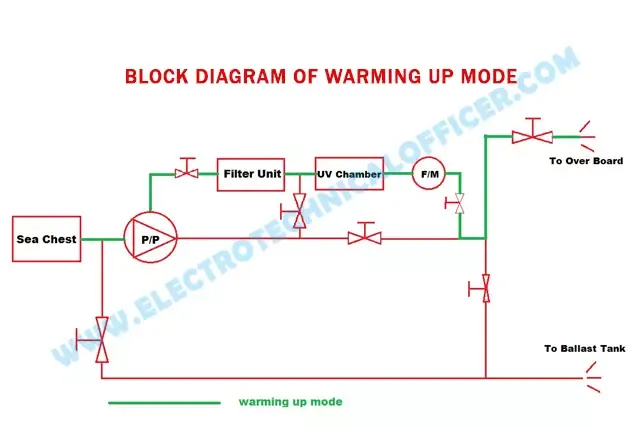
A. Warming Up Mode-UV Treatment Method
UV lamp
requires sufficient time to reach the full power which is approx. 5 min so it
is necessary to start up the warm-up mode before the ballasting or de-ballasting mode for the better performance by the system.
In this case, water pumped
from the sea chest and passes through the filter unit and UV chamber the
treated water discharged to sea through the overboard valve instead of the
ballast tank until the operator changed the ballasting mode.
Water Flow: sea chest Ballast pump ---> Filter Unit ---> UV Chamber ---> Flow Meter ---> O/B
B. Ballasting Mode-UV Treatment Method
During
ballasting operation water pumped from the sea chest and passed through the
main filter unit for the pre-treatment to filter the large planktons, larva,
sediments and other marines micro-macro organism by the 50-micron candle type
filter.
It is equipped with the auto back
washing assembly to pump out the filtered particles from the filtration unit
without interrupting the ballast operation and the backwash takes place
automatically when differential pressure reaches the set point or the timer set
value for the back-washing operation.In the UV chamber, the primary treatment process takes place by the high-intensity medium pressure ultraviolet and depending
upon the flow rate of the ballast water, the UV lamp ballast is activated and de-activated by the PLC to maintain the sufficient UV dose to kill the marine the organism in the primary treatment. It requires the high voltage power for the
medium pressure lamp inside the UV chamber, this type of UV treated BWTS is
not using any kind of chemicals during ballasting except titanium dioxide-based
UV treatment system which can produce the oxygen and hydroxyl (OH) chemicals
for the disinfection process which have the strong disinfectant. 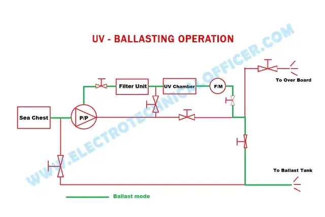

Water Flow: sea
chest ---> Ballast pump ---> Filter Unit ---> UV Chamber ---> Flow Meter ---> B/T
C. De-Ballasting Mode-UV Treatment Method
During de-ballasting operation the
water sucked from the ballast tank instead of the sea chest and passes through
the UV chamber for the second UV dose during de-ballasting. Because after the
ballasting operation the marine organism can reproduce in the ballast water
tank hence it is very important that the water should retreat before
discharge to the shore Valves are lined
up automatically when the de-ballasting mode operation commenced and the valves
are lined up and operated by the monitoring and control unit (PLC).
Water Flow: Ballast tank ---> Ballast pump ---> UV Chamber ---> Flow Meter ---> O/B
D. By-Pass Mode-UV Treatment Method
In this mode, the system can run
without the treatment cycle in case of any stoppage due to malfunction or any
local regulation’s involved to avoid using the treatment system, all
precautions to be taken while by-passing the ballast water treatment system and
relevant persons to be duly informed.





2 Comments
Thank you sir
ReplyDeleteSir plz tell regulations of BWTS ?
ReplyDeleteWe love to hear your comments on this article, so that we may better serve you in the future.